WILLIAM H. MASTERMAN AND JOSEPH P. MAGNEY, OF ALLEGAN, MICHIGAN, ASSIGNORS TO MICHIGAN ENGINE CO.,
OF ALLEGAN, MICHIGAN, A CORPORATION
ROTARY ENGINE.
Specification forming part of Letters Patent No. 728,263, dated May 19, 1903.
Application filed July 22, 1902, Serial No. 116,581. (No model).
To all whom it may concern:
Be it known that we, William H. Masterman
and Joseph P. Magney, of Allegan, Allegan county, Michigan, have invented certaine new and useful
Improvements in Rotary Engines; and we hereby declare that the following is a full, clear, and exact
description thereof, reference being had to the accompanying drawings, which form part of this
specification.
This invention is an improved rotary-piston engine, and its object
is to provide an efficient compact engine having two sets of geared rotary pistons being set in advance
of the other, so that the engine will at no time be dead-centered. The admission of steam to both sets
of cylinders is contraolled by a single tubular rotary valve, which is geared to one of the piston-shafts,
and the exhaust-steam is admitted into a housing inclosing the engine proper and will lubricate the
external gearing and keep all the working parts at a substantially uniform temperature.
The invention therefore consists in teh novel construction and combination of parts hereinafter described
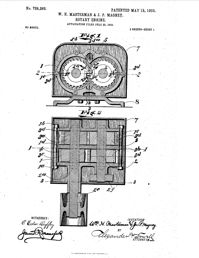
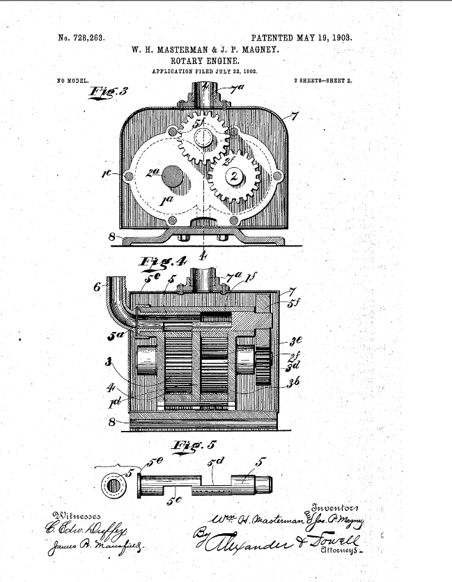
and claimed, and the accompanying drawings illustrate and engine embodying the invention, Figure 1 being a
transverse section of the engine on line 1 1, Fig. 2; Fig. 2, a horizontal section of the engine on line
2 2, Fig. 1; Fig. 3, a vertical section on line 3 3, Fig. 2; Fig. 4. a longitudinal section on line 4 4,
Fig. 3, and Fig. 5 is a detail view of the valve.
The engine-casing is composed of a central casting
by through-bolts 1o, suitably nutted, as shown. The casting 1 is divided into two compartments by
a transverse partition 1d, and at each side of said partition are two parti-cylindric working
chambers, within which the pistons operate. Extenging axially through the working chambers and journaled
in suitable bearings in the end castings are a pair of parallel shafts 2 2a, and fixed on shaft 2
within the adjacent working chambers are two rotary pistons 3 and 3b, which respectively coact
with opposed rotary pistons 3a and 3c, fixed on shaft 2a within the adjacent
working chambers. The pistons are all gear-pistons, the teeth of pistons 3 3a meshing; also, the
teeth of pistons 3b 3c mesh, and therefore neither piston can rotate without a
corresponding rotation of the other pistorn. The gear-pistons are each provided with an elongated piston-tooth
3d, which is adapted to fill the cross-section of the annular space in teh working chambers 4 4
concentric to the piston and to serve as a moving abutment against which the steam or other propelling medium
acts to rotate the piston. It will be noted that the pistons are rotated solely by the action of the impelling
fluid against these abutments 3d and that the intermeshing gear-teeth on the opposed pistons are employed
solely as gearing there between to cause them to rotate synchronously and are not useful as abutments. In order
to permit the abutments 3d to pass at the meshing-point of the gears, each piston has a concavity
3e, into which the opposed abutment projects when teh abutments are passing the meeting-point of the
pistons, as shown in full lines in Fig.1.(more information provided in the patent documentation)
|

 Click to enlarge
Photos from patent
application |


 Return
To Home Page
